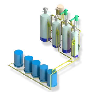
Carbonation
Phosphoflotation
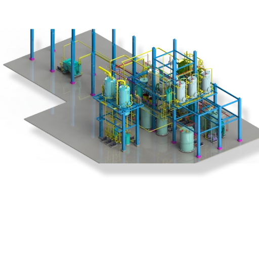
The main principle of clarification process is to remove turbidity and colour from the screened melt by means of sedimentation (flotation type) technique. Screened melt from vibratory screens is pumped DCH (Direct Contact Heater), which raises the temperature of the melt to about 85 oc. The melt then flows to the reaction tank where lime sucrate, phosphoric acid, colour precipitant are automatically dosed into the first chamber of the reaction tank in proportion to the flow rate of the melt. Lime sucrate is dosed to neutralize the effect of phosphoric acid at a controlled pH of 7.0. Colour precipitant is added to increase the level of decolourisation.
The resulting calcium phosphate suspension scavenges colour, turbidity, suspended solids and other non-sucrose materials. The melt then flows over to the aerator where specially designed aerator disperses finely divided air bubbles into the treated melt. On leaving this tank, melt flows into the flotation clarifier by gravity with continuous addition of flocculant into the melt stream proportion to the melt flow rate. As the liquor enters the large central tube of the clarifier the flocculant is gently stirred into the liquor by static system which is inbuilt in central shaft.
The primary flocs and finely dispersed air are coagulated by the flocculant solution to form large aerated flocs that float to the surface of the clarifiers forming a scum layer. The scum is removed from the surface by the scum scrappers and is discharged into the clarifier’s peripheral scum trough from where it flows by gravity to the scum holding tank. The clarified liquor flowing down to the bottom of the clarifier enters the outlet ring main and rises up to the weir box and flows into the Clear Melt Tank.
Brine / Rinse Water Recovery System
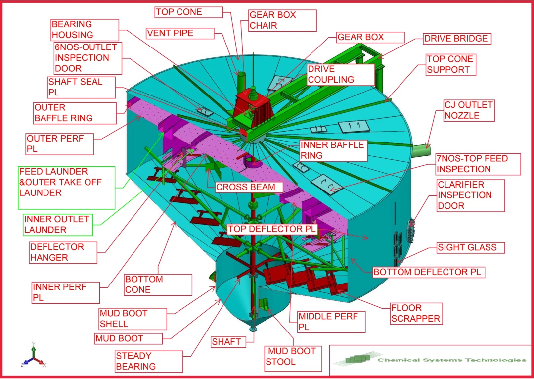
SRT for Juice Clarification
In SRT, the entry and distribution of the juice are effected by a circular channel of radius equal to two-thirds of that of the subsider; it overflows by a notched channel into an annular down take, which delivers the juice at the mid-height of the vessel; it then meets a deflector of double slope which distributes it laterally in the equipment.
The settled mud accumulates on the bottom, where it is scraped towards a mud well and removed. The scrapers are carried on rotating arms. The clarified juice overflows by two notched gutters, both circular and concentric; the first or inner one is of radius one-half or two-thirds that of the entry channel, the second approximately half way between the latter and the outer wall of the tank. Fixed scrapers avoid accumulation of mud on the double-sloped deflector which is fixed to the rotating arms.
Decanter Based Mud Removal System
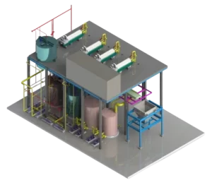
Multi Bed Filter (MBF)
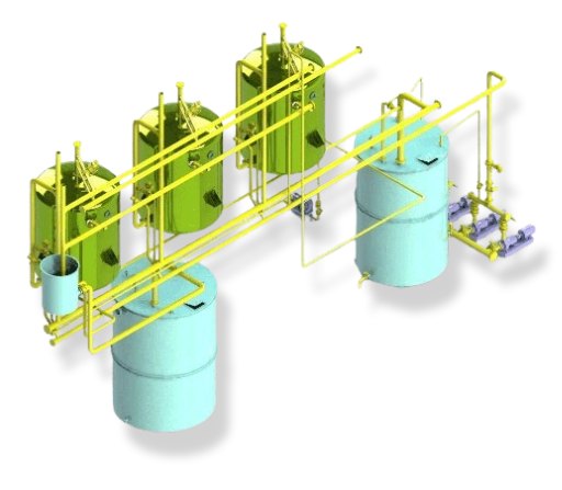
The purpose of the Multi Bed Filter (MBF) is to remove suspended solids carried over from raw melt clarification before the liquor passes on to the next stage of the refining process. The filter operates in a similar fashion to sand filters employed in the water industry; however, the bed used is far more complex. The operation of ordinary down-flow mono-bed filters is hampered by surface blinding where only the uppermost part of the bed is effectively used as the filtering media.
Since most fluids to be filtered contain a range of suspended solid sizes, the ideal bed has larger particles of media at the top with larger interstitial spaces, with smaller particles of media at the base. Grading the bed in this way ensure that the larger particles are trapped in the top of the bed whilst medium and smaller- sized particles pass through the relatively loose upper layers to be trapped in the lower part. Thus, good use is made of the entire depth of the filtration bed.
Ion Exchange
PAC/GAC
The filtered liquor from the deep bed filter is heated in the heat exchanger to 85 oc and then mixed with a mixture of powdered activated carbon and filter aid in the carbon reaction tank. The retention time in the reaction tank is 20-30 minutes and then the liquor is pumped to membrane filter press. Initially, the filter id pre-coated with filter aid and then the liquor is filtered. The filtration process is continued until the filter pre-set pressure value is achieved and then the filter undergoes draining, de-sweetening, air squeezing, drying and cake wash cycle.
The filter operation sequence is as follows:
Pre-Coating -Y Production Recycle -5 Production Blowback 1 -Y Cake Wash Blowback 2 Air Squeezing -Y Cake Drying Cake Discharge

